Measurement Environment
The measurement setup was installed in the anechoic chamber at NTNU Trondheim, Norway. The chamber is equipped with sound absorbing wedges on all walls and provides free field characteristics down to a frequency of 75 Hz (room dimensions: 7.5 m × 5.9 m × 5.9 m, 260 m3). For installation purposes, the room features an L-shaped metal grid that is mounted to the floor by circular steel tubes. In this measurement setup, a removable rail system that connects the two platforms of the L-shape was additionally used to carry a Norsonic NOR265 turntable by means of a movable metal sled. The turntable was remote-controlled via an RS-232 interface from a standard PC outside the anechoic chamber. The same PC was used for performing the measurement series by means of the measurement software WinMLS. The tool was used to compute the excitation signal (exponential sweep, 2.73 sec long) that was then played back by a loudspeaker and recorded by two microphones at the same time in order to obtain the respective impulse responses. The measurement system consisted of two Brüel & Kjær (B&K) 4149 free-field equalized 1/2” microphone capsules with Norsonic 1201 preamplifiers, a Norsonic Frontend 336 microphone amplifier, a LynxTwo soundcard, a Quad 50E power amplifier, and two different measurement loudspeakers.
Measurement Loudspeakers
Two loudspeakers with strongly differing directivities were used for the measurement series. The first series was carried out with the high frequency unit of a three-way measuring loudspeaker system with omni-directional radiation characteristics. The speaker was developed at the Institute of Technical Acoustics (ITA) and is designed as a PVC-sphere of 10 cm diameter equipped with 12 tweeters. The small cabinet is made possible by means of center-magnet drivers featuring neodymium with an overall diameter of only 36 mm. The unit radiates omni-directionally up to 5 kHz but has little output capability below 1 kHz. Above 5 kHz the loudspeaker directivity loses its spherical characteristics as it gets more and more dominated by the radiation pattern of each driver. More information on this high frequency unit together with a detailed description of the whole three-way loudspeaker system can be found in [1].
The second measurement series was carried out using the measurement loudspeaker developed by the acoustics group at NTNU. The unit consists of a single two-inch driver (Aurasound NSW2-326-8A-120) that is mounted at the end of a 37 cm long, 5 cm diameter PVC tube where the other end is closed. This loudspeaker covers a much broader frequency range than the previous one, from 200 Hz up to 20 kHz, caused by the larger excursion abilities of this two-inch driver, together with the smoothly increasing directivity of the single driver. However, the single driver system also demands for a very precise positioning to be able to model the directivity with high accuracy. For this reason, the loudspeaker features also a removable aiming device that functions like an iron sight of a rifle, but with a second notch instead of a bead. This enables an easy and very accurate adjustment of the loudspeaker along a laser ray that is shot from a target position. The directivity of the single-driver speaker is indicated by the frequency responses for various angles (see download section). For the specific scattering objects used in this study, radiation angles up to around 28 degrees off-axis will hit the object, but most parts of the scattering objects will be within angles up to around 15 degrees off-axis. Therefore, it can be seen that up to 5 kHz, the narrow- band level is within 0 to −1 dB. For slightly more relaxed requirements, the level is within 0 to -2 dB up to 8 kHz.
Measurement Microphones
Two microphones were used to measure the respective impulse responses behind the noise barrier model. The microphones were calibrated to 94 dB at 1 kHz using a B&K 4231 calibrator. A special T-shaped microphone stand was constructed to measure at two positions at the same time consisting of two steel rods where the top rod was perpendicular to the other rod and offered microphone mountings on each side with a total distance of 1 meter in between. In addition, a laser device was mounted on top of the stand, centered between the two microphones and pointing in parallel to their direction. The great benefit of this type of construction is that it enables an accurate alignment of the stand by means of both, a cross laser device that points from the target position to the top center of the stand and the top-mounted laser device that points from the stand to the target position.
Scale Model of a Noise Barrier
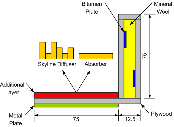
A 1:4 scale model of a simple noise barrier was constructed as test object. The model was basically a box with a perpendicular ground layer on one side, with both parts made from 15 mm plywood. The box was filled up with mineral wool and 2 mm bitumen patches were attached to the box’s inner faces to reduce vibrations. The outer faces were filled, sanded, primed, painted, and polished in order to maintain rigid and smooth surfaces. Additional layers were mounted on the ground layer in order to change the object’s acoustical properties to a large degree and thus being able to generate measurement series that differ considerably.
[nggallery id=5]
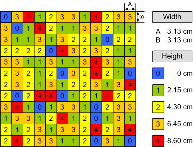
Four different layers were additionally attached during these measurement series: 3 absorber plates and 1 self-constructed skyline-diffuser. The absorbers were made from 25 mm and 50 mm slabs of polyurethan fibres and fibreglass wool, respectively. The skyline-diffuser was designed to scatter uniformly in the frequency range from 2000 Hz to 5500 Hz. A single diffuser unit was assembled from 131 massive columns with the same quadratic cross section (3.13±0.05 cm edge length) and material (oak), but different heights (13 pieces of 0 cm, 38 pieces of 2.15 cm, 38 pieces of 4.30 cm, 40 pieces of 6.45 cm, and 15 pieces of 8.60 cm height, with an accuracy around 0.05 cm). This resulted in a 12 by 12 matrix with a total edge length of 37.5 cm following a special pattern that is shown in the figure below. To cover the whole ground layer four identical skyline diffuser units were constructed and mounted side-by-side with an overall weight of about 18 kg. Due to the large weight difference between the different cases, a 4 mm thick metal plate was mounted to the rear side of the ground layer for the non-diffuser cases in order to keep a balanced weight distribution across all cases.
 |
 |
|
Noise barrier construction plan. Dimensions in cm. |
Column-pattern of the skyline diffuser. |
Measurement Procedures
The measurements were carried out in two subsequent phases. At first, the turntable, loudspeaker and calibrated microphones were installed inside the anechoic chamber using laser devices for accurate positioning. All mountings were covered with fibreglass wool strips, which were fine-tuned by analyzing trial measurements and reducing unwanted reflections that came from certain reflecting parts.
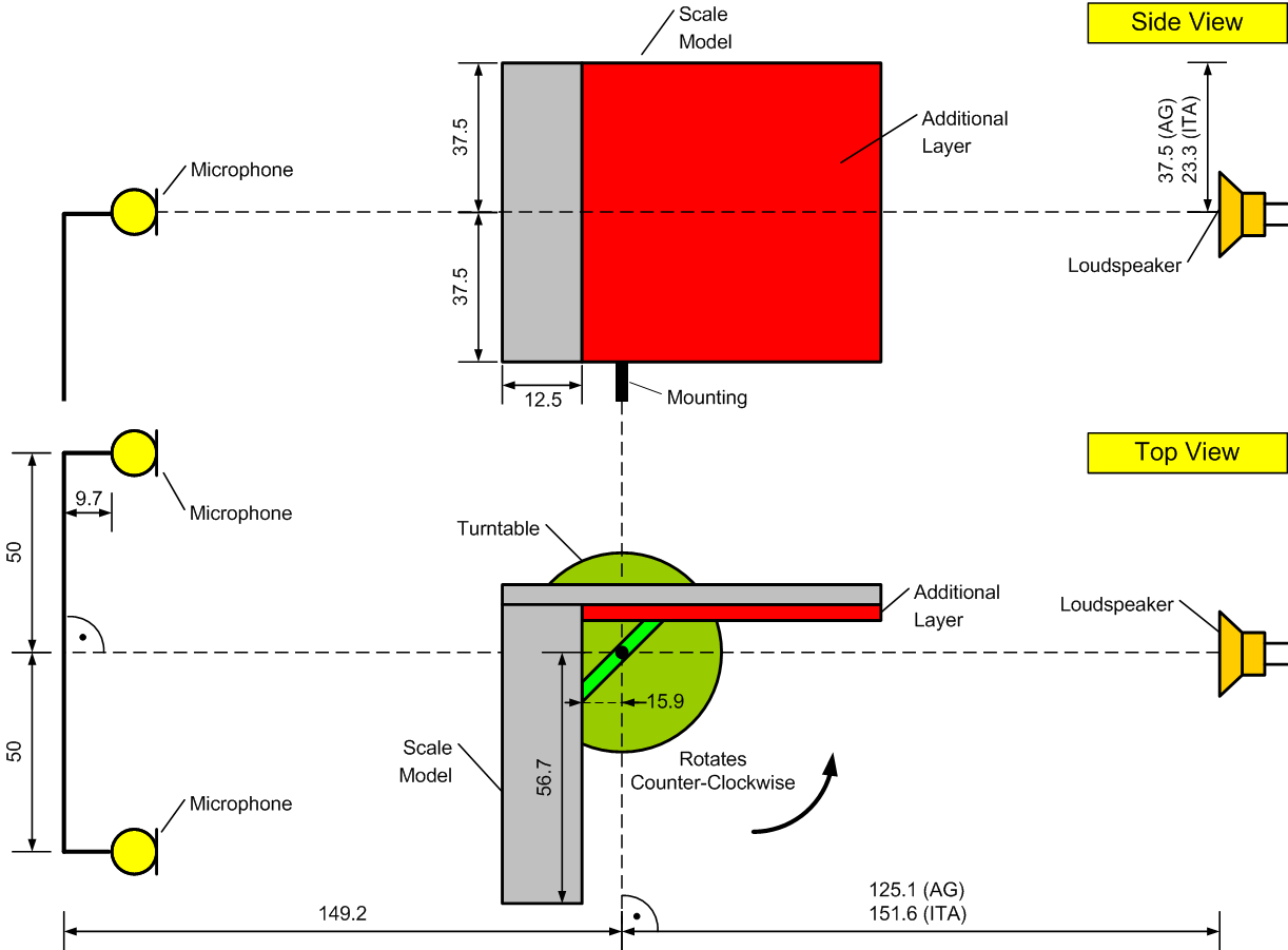
These measurements were also used for an additional checkup of the setup by comparing level and time of the first arriving impulse (direct sound) at both microphone positions. As the distance from the loudspeaker to both microphones was equal, these impulse responses had to be very similar. After optimizing the setup, ‘free field’ measurements were carried out for both loudspeakers in order to construct inverse equalization filters that are required for removing the influence of the loudspeaker response from the measurements. Then the scale model was attached to the turntable using a special mounting that provided a balanced and stable revolution around the model’s rotation axis. Fibreglass wool was additionally wrapped around this mounting to reduce unwanted reflections. An assembly plan of the measurement setup is shown below. Here, the distances to the loudspeakers and microphones, respectively, refer to the estimated acoustic centers across the frequency range of interest.
[nggallery id=6]
During phase two the actual measurements of scattering/diffraction from the scale model were carried out. The measurements were divided in two main series, one using the ITA loudspeaker and one using the NTNU loudspeaker. Each main series consisted of five subseries with different model setups: (1) no additional ground layer (rigid surface), (2–4) absorbing ground layers (soft edges), and (5) scattering ground layer (skyline diffuser). The turntable rotated the model counter-clockwise in steps of one degree with a pause of 10 s between each measurement to ensure that the model had reached a stable position. This resulted in 360 measurements for each microphone per subseries, where the model’s initial position (0 degree) is shown in the figure below.
 |
|
Assembly plan for the measurement setup. All dimensions are in cm. |
More Details & Downloads
Downloads
| Sampling Frequency | 48000 Hz |
| Delay of the sound card | delay_soundcard, 2.2035e-3 [sec] |
| Inverse Impulse Response, Louspeaker NTNU | NTNU_IRinv |
| Rigid, 360° in steps of 1 degree, 2 microphones | Rigid |
| Absorber_1, 360° in steps of 1 degree, 2 microphones | on demand |
| Absorber_1, Absorption Coefficients | on demand |
| Absorber_2, 360° in steps of 1 degree, 2 microphones | on demand |
| Absorber_2, Absorption Coefficients | on demand |
| Absorber_3, 360° in steps of 1 degree, 2 microphones | on demand |
| Absorber_3 Absorption Coefficients | on demand |
| Schröder Diffuser, 360° in steps of 1 degree, 2 microphones | on demand |
| Schröder Diffusor, Scattering Coefficients | on demand |
References
1. G. K. Behler and S. Müller, Technique for the derivation of wide band room impulse response, Proc. of the EAA symposium on Architectural Acoustics, Madrid, Spain, Oct. 16-20, 2000.